- 您现在的位置:买卖IC网 > Sheet目录324 > EVAL-ADUC7060QSPZ (Analog Devices Inc)KIT DEV QUICK START ADUC7060
�� ��
��
��ADuC7060�
�PULSE-WIDTH� MODULATOR�
�PULSE-WIDTH� MODULATOR� GENERAL� OVERVIEW�
�The� ADuC7060� integrates� a� 6-channel� pulse-width� modulator�
�(PWM)� interface.� The� PWM� outputs� can� be� configured� to� drive�
�an� H-bridge� or� can� be� used� as� standard� PWM� outputs.� On�
�power-up,� the� PWM� outputs� default� to� H-bridge� mode.� This�
�ensures� that� the� motor� is� turned� off� by� default.� In� standard�
�PWM� mode,� the� outputs� are� arranged� as� three� pairs� of� PWM�
�pins.� Users� have� control� over� the� period� of� each� pair� of� outputs�
�and� over� the� duty� cycle� of� each� individual� output.�
�Table� 81.� PWM� MMRs�
�In� all� modes,� the� PWMxCOMx� MMRs� control� the� point� at�
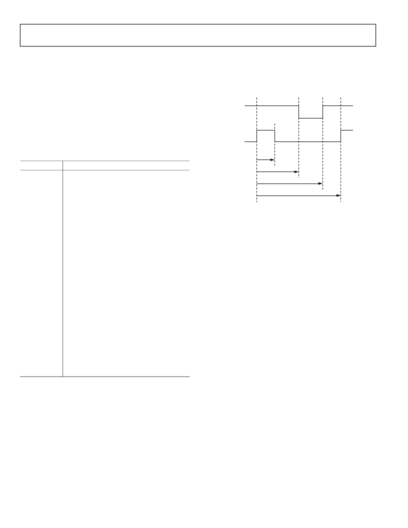
�which� the� PWM� outputs� change� state.� An� example� of� the� first�
��HIGH� SIDE�
�(PWM0)�
�LOW� SIDE�
�(PWM1)�
�PWM0COM2�
�MMR� Name�
�Description�
�PWMCON�
�PWM0COM0�
�PWM0COM1�
�PWM� control.�
�Compare� Register� 0� for� PWM� Output� 0� and�
�Output� 1.�
�Compare� Register� 1� for� PWM� Output� 0� and�
�PWM� Output� 1.�
�PWM0COM1�
�PWM0COM0�
�PWMLEN0�
�Figure� 25.� PWM� Timing�
�PWM0COM2�
�PWM0LEN�
�PWM1COM0�
�PWM1COM1�
�PWM1COM2�
�PWM1LEN�
�PWM2COM0�
�PWM2COM1�
�PWM2COM2�
�PWM2LEN�
�PWMICLR�
�Compare� Register� 2� for� PWM� Output� 0� and�
�PWM� Output� 1.�
�Frequency� control� for� PWM� Output� 0� and� PWM�
�Output� 1.�
�Compare� Register� 0� for� PWM� Output� 2� and�
�PWM� Output� 3.�
�Compare� Register� 1� for� PWM� Output� 2� and�
�PWM� Output� 3.�
�Compare� Register� 2� for� PWM� Output� 2� and�
�PWM� Output� 3.�
�Frequency� control� for� PWM� Output� 2� and� PWM�
�Output� 3.�
�Compare� Register� 0� for� PWM� Output� 4� and�
�PWM� Output� 5.�
�Compare� Register� 1� for� PWM� Output� 4� and�
�PWM� Output� 5.�
�Compare� Register� 2� for� PWM� Output� 4� and�
�PWM� Output� 5.�
�Frequency� control� for� PWM� Output� 4� and� PWM�
�Output� 5.�
�PWM� interrupt� clear.�
�The� PWM� clock� is� selectable� via� PWMCON� with� one� of� the�
�following� values:� UCLK� divided� by� 2,� 4,� 8,� 16,� 32,� 64,� 128,� or�
�256.� The� length� of� a� PWM� period� is� defined� by� PWMxLEN.�
�The� PWM� waveforms� are� set� by� the� count� value� of� the� 16-bit�
�timer� and� the� compare� registers� contents� as� shown� with� the�
��The� low-side� waveform,� PWM1,� goes� high� when� the� timer�
�count� reaches� PWM0LEN,� and� it� goes� low� when� the� timer�
�count� reaches� the� value� held� in� PWM0COM2� or� when� the�
�high-side� waveform� (PWM0)� goes� low.�
�The� high-side� waveform,� PWM0,� goes� high� when� the� timer�
�count� reaches� the� value� held� in� PWM0COM0,� and� it� goes� low�
�when� the� timer� count� reaches� the� value� held� in� PWM0COM1.�
�Rev.� 0� |� Page� 70� of� 100�
�发布紧急采购,3分钟左右您将得到回复。
相关PDF资料
EVAL-ADUC845QSPZ
KIT DEV QUICK START ADUC845
EVAL-ADUM3070EBZ
BOARD EVAL FOR ADUM3070
EVAL-SDP-CB1Z
BOARD EVALUATION FOR SDP-CB1
EVB51JM128
BOARD EVAL FOR MCF51JM128 MCU
EVBQE128
BOARD EVAL FLEXIS QE128 FAMILY
F2068
PNL FIBERGLASS 18.44X14.44" WHT
FAN3100CMPX
IC GATE DRVR SGL CMOS 2A 6MLP
FAN3111CSX
IC GATE DVR 1CH 1A LOW SOT23-5
相关代理商/技术参数
EVAL-ADUC7060QSPZU1
制造商:Analog Devices 功能描述:
EVALADUC7060QSPZU2
制造商:Analog Devices 功能描述:QUICK START DEVELOPMENT SYSTEM - Boxed Product (Development Kits)
EVAL-ADUC7061MKZ
功能描述:开发板和工具包 - ARM Quick Start Development System
RoHS:否 制造商:Arduino 产品:Development Boards 工具用于评估:ATSAM3X8EA-AU 核心:ARM Cortex M3 接口类型:DAC, ICSP, JTAG, UART, USB 工作电源电压:3.3 V
EVAL-ADUC7061MKZ
制造商:Analog Devices 功能描述:ADUC7061MKZ EvaluationBoard
EVAL-ADUC7061MKZU2
制造商:Analog Devices 功能描述:PN may be NE CE 制造商:Analog Devices 功能描述:EVALUATION CONTROL BOARD - Boxed Product (Development Kits)
EVAL-ADUC7121QSPZ
功能描述:BOARD EVALUATION FOR ADUC7121 RoHS:是 类别:编程器,开发系统 >> 通用嵌入式开发板和套件(MCU、DSP、FPGA、CPLD等) 系列:MicroConverter® ADuC7xxx 标准包装:1 系列:PICDEM™ 类型:MCU 适用于相关产品:PIC10F206,PIC16F690,PIC16F819 所含物品:板,线缆,元件,CD,PICkit 编程器 产品目录页面:659 (CN2011-ZH PDF)
EVALADUC7121QSPZU1
制造商:Analog Devices 功能描述:QUICK START DEVELOPMENT SYSTEM - Boxed Product (Development Kits)
EVAL-ADUC7122QSPZ
功能描述:BOARD EVALUATION FOR ADUC7122 RoHS:是 类别:编程器,开发系统 >> 通用嵌入式开发板和套件(MCU、DSP、FPGA、CPLD等) 系列:MicroConverter® ADuC7xxx 标准包装:1 系列:PICDEM™ 类型:MCU 适用于相关产品:PIC10F206,PIC16F690,PIC16F819 所含物品:板,线缆,元件,CD,PICkit 编程器 产品目录页面:659 (CN2011-ZH PDF)